 |
|||
|
|
|||
|
|
|||
| ||||||||||
|
|
 TM 5-5420-279-23
NOTE
The top bearing pads can be changed with the A-Frame deployed.
It is necessary to deploy the A-Frame, three launch beams and the far bank support. The
articulator cylinders must be disconnected from the slide frame and stowed. The A-Frame
must then be raised to allow access to the bottom wear pads on the upper sliding section.
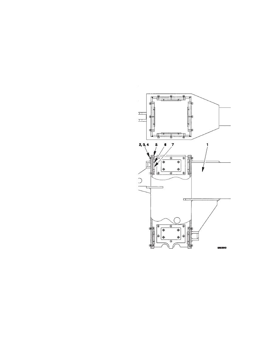
Top view
a.
Remove
(1)
The left and right A-Frame upper
sliding section (1) each have eight
bearing pads.
(2)
Note the position of each bearing pad
before removing it. The bearing pads
must be fitted in the same position
during installation.
(3)
Remove the socket head screws (2),
lock washers (3) and plain washers (4).
Discard the lock washers (3).
(4)
Slide the bearing pad holder (5) out of
the upper sliding section (1).
NOTE
The bearing pad (7) must be replaced
when the distance between the head of
screws (6) and the surface of the bearing
pad (7) is 1/16 inch (1.5mm).
(5)
Remove the screws (6) securing the
bearing pad (7) to the bearing pad
holder (5) and retain the shim(s).
NOTE
The shims are matched to the bearing pad
holders, keep them together for
installation.
(6)
Remove the bearing pad (7).
(7)
Inspect components for wear, damage
and corrosion.
(8)
Examine bolt heads and threads for damage.
(9)
Replace components as required.
5-102
|
|
Privacy Statement - Press Release - Copyright Information. - Contact Us |
