 |
|||
|
|
|||
|
Page Title:
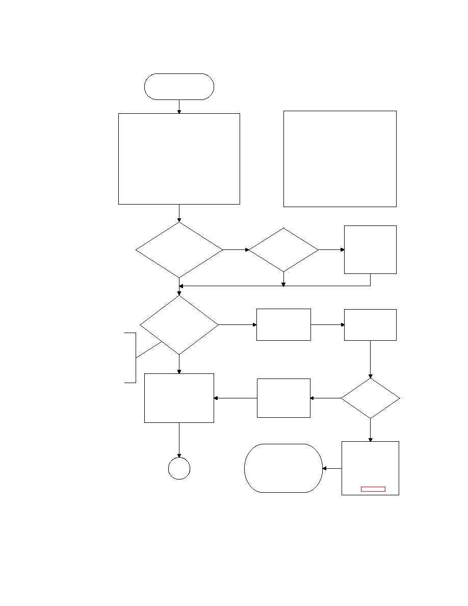
TSUM - 3-019 Carriage Drive Failure (Low Bank Drive In) Part 1 |
|
||
| ||||||||||
|
|
 TM 5-5420-279-23
Carriage will not drive in
(Low Bank)
W ARNING
For the Carriage to drive in (Low Bank) the following
prerequisite conditions m ust be met:
CRUSH INJURY. BEFORE CARRYING OUT
* Neutral gear selected
TROUBLESHOOTING INVOLVING SV10, A
* Parking brake applied
SUSPENDED OR PART BUILT BRIDGE M UST
* Tail Lift Pendant connected & powered
BE M ADE SAFE EITHER BY COMPLETING THE
* Chest Pack connected & powered
BUILD OPERATIONS IN BACK-UP MODE OR
* 4 Position Switch at position 4
BY RETRIEVING THE BRIDGE.
* Ensure E-STOP RESET satisfactory
* A-Fram e unfolded
CRUSH INJURY. A SUSPENDED BRIDGE W ILL
* A-Fram e rotated
M OVE IF SV10 IS MANUALLY OPERATED AND
* Slide Fram e extended
THE CHEST PACK RIGHT-HAND JOYSTICK IS
* Relax Pins withdrawn & Limit Switches closed
MOVED FROM THE CENTRAL POSITION
* Chest Pack in Carriage Drive Low Bank m ode
CAUSING ACTIVATION OF OTHER SOLENOID
* RH Joystick moved backward from centre
VALVES.
Are the
Power down & replace
following Mim ic
Perform
defective Mimic Panel.
Panel captions lit?-PV1a,
lam p test on
No
No
To replace Electrical
SV5, SV6, SV7, SV10 (see
Mimic Panel.
Enclosure see
W ARNING), SV13a,
Are all lam ps
m aintenance
SV14a &
lit?
procedure 5-049
SV15a
Yes
Yes
Are the
following solenoid
Disconnect connectors
connector LEDs lit?- SV5,
Insert probes of DMM
No
from listed solenoids.
SV6, SV7, SV10 (see
into sockets 1 & 2 of
See maint procedure
W ARNING), SV13a,
each connector
5-141
SV14a &
NOTE
SV15a
Solenoids SV5, SV6, SV7 &
SV10 are located on the
Launch Frame Pilot
Yes
Manifold. Solenoids SV13a,
SV14a & SV15a are located
on the Launch Frame W inch
Control Manifold
Disconnect solenoid
connectors from above listed
Replace solenoid
solenoids. See maint
Is 24V
harness if connector
Yes
procedure 5-141. Connect
solenoid supply
LED not lit. See
DMM across solenoid coil
present?
m aintenance
pins. See resistance check in
procedure 5-139
maint procedure 5-124
No
Power down & check
Replace faulty harness or
harness continuity from
Launch Frame Enclosure as
listed solenoids to
appropriate using the following
Launch Fram e
Go to
m aintenance procedures:-
Enclosure using the
Part 2
Harness 5-139
cable routing tables in
Launch Frame Enclosure
section 3.6
5-049
of Chapter 3
|
|
Privacy Statement - Press Release - Copyright Information. - Contact Us |
