 |
|||
|
|
|||
|
|
|||
| ||||||||||
|
|
 TM 5-5420-279-23
1-10-23 Launch Beam
a.
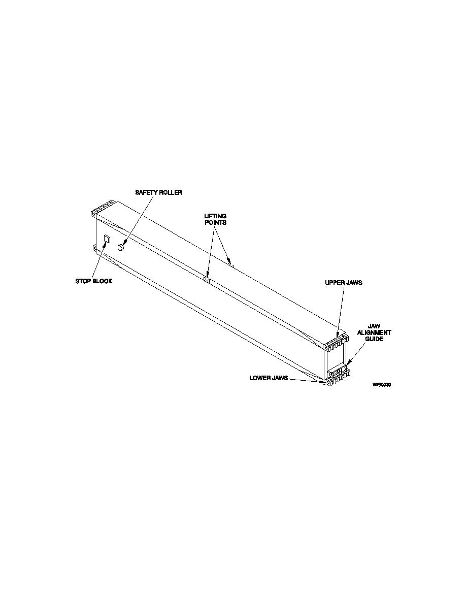
The launch beam, when deployed, provides support for the bridging modules and
accommodates the forward and rear carriages during bridge construction. It comprises eight
beam modules which connect together to form the launch beam. Seven modules are transported
to the bridging site on a PLS flatrack carried on an M1076 PLS trailer and a forward launch beam
carried in the launch frame of the launcher vehicle.
b.
The modules are of traditional web chord construction in aluminum alloy 232B and feature
identical top and bottom extrusions, which terminate with welded-in jaw arrangements. A series of
diaphragms to absorb torsional loads are built in along the length of the beam. The side webs
have stiffeners to prevent buckling and the top chord of each beam incorporates lifting points.
Fig 1.7 Launch Beam
c.
The welded-in jaw arrangements at the top and bottom of each module end are identical
and multi-lugged. The forward jaws of each module are aligned to contact the jaw lugs of the
beam module already positioned in the launch frame and then pinned in position; upper jaws first
and then the lower jaws. The lower jaws being aligned by a mount resilient jaw guide system.
d.
The launch beam connecting pins incorporate a flat on the head of the pin, which allows
insertion into the lugs in one position only. This allows insertion of the pin locking clips also in one
position only and prevents them causing damage to the rollers during beam deployment. The
forward launch beam module provides a frame mounting for the far bank support.
e.
The launch beams incorporate safety rollers and stop blocks. The safety rollers raise the
launch beam stop on the launch frame during booming so that the stop block on the proceeding
1-16
|
|
Privacy Statement - Press Release - Copyright Information. - Contact Us |
