 |
|||
|
|
|||
|
|
|||
| ||||||||||
|
|
 TM 5-5420-279-23
circumstances, such as loss of electrical power, direct manual operation is possible from the
selector valve located at the rear of the chassis in conjunction with manual operation of the
cylinder solenoids.
b.
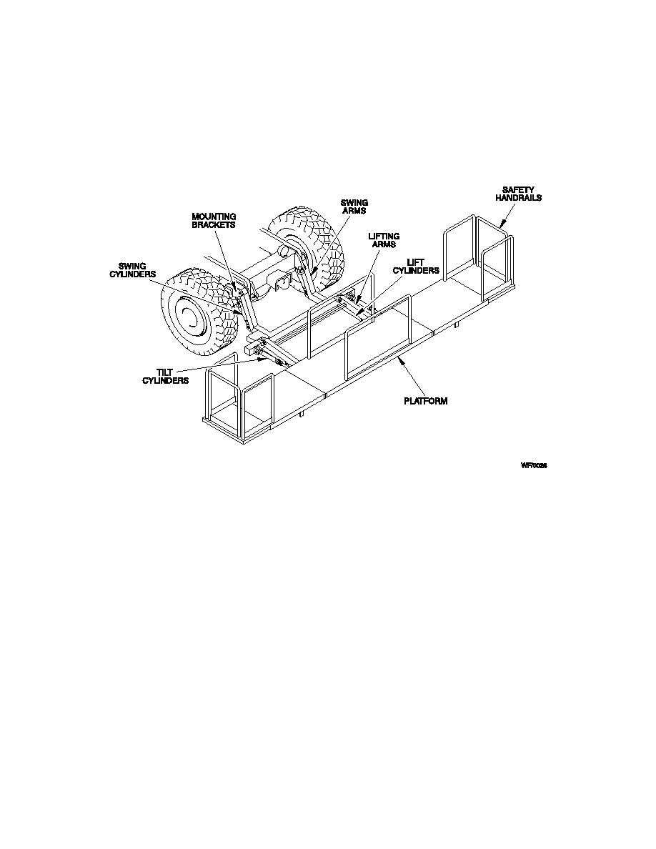
An emergency stop button is located adjacent to the selector switches and on the tail lift
handset. The maximum height of the platform above ground level is 4 ft 10 in (1.47 m).
Fig 1.3 Tail Lift
1-10-8
A-Frame
The A-Frame is of steel construction and when deployed, stabilizes the rear of the vehicle and
provides a level home bank platform for the launch frame, launch beam and bridging modules. It
comprises upper and lower transverse beams, foldout stabilizer legs, hydraulic cylinders and
hydraulic control valves.
1-10-9
Upper A-Frame Transverse Beam
a.
The upper A-Frame transverse beam spans the rear of the vehicle, supports the launch
frame with its associated equipment and provides the upper hinge points for the outer A-Frame
legs.
b.
When the A-Frame is deployed, the beam is pinned at its hinge position to the outer legs
during erection of the launch beam and bridge modules.
c.
The launch beam and the launch frame, together with its associated equipment, move
vertically on the outer A-Frame legs by the operation of hydraulic cylinders on the upper section
1-9
|
|
Privacy Statement - Press Release - Copyright Information. - Contact Us |
