 |
|||
|
|
|||
|
Page Title:
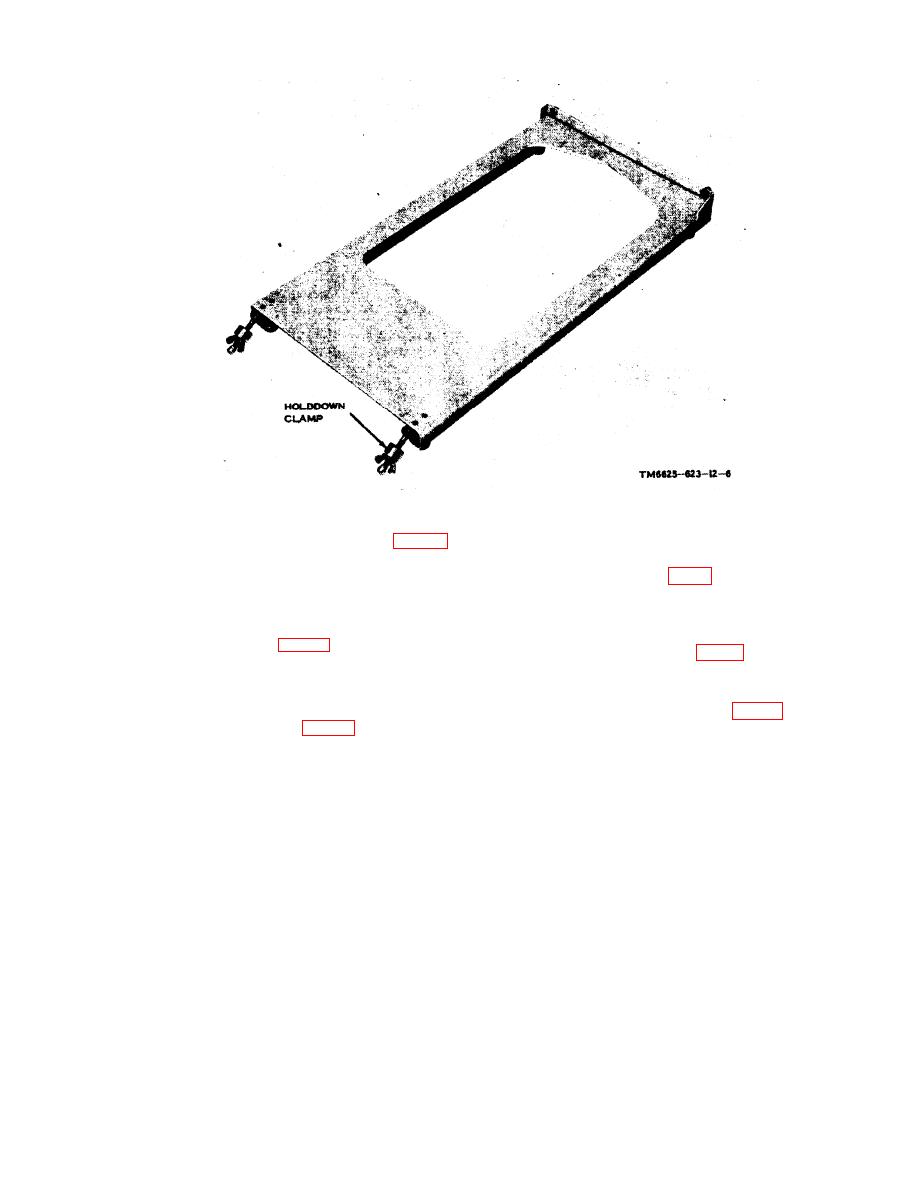
Figure 1-5. Radio test fixture. |
|
||
| ||||||||||
|
|
 TM 11-6625-623-12
dummy load when testing the rf translator
module of the receiver-transmitter.
The autopositioner frame, dial, pointer, and
three machine screws are used for alignment
and testing the autopositioner in the receiver-
device for the high-frequency (hf) signal gen-
erator.
cycle (mc) and 8-30 mc capacity dividers are
mc detector is used to transmit noise measure-
used as voltage dividers in the indicated fre-
ments.
quency ranges.
neutralizing detector is used in driver and feed-
back neutralizing adjustments.
frequency (rf) translator load is used as a
9
|
|
Privacy Statement - Press Release - Copyright Information. - Contact Us |
