 |
|||
|
|
|||
|
|
|||
| ||||||||||
|
|
 TM 11-6625-623-12
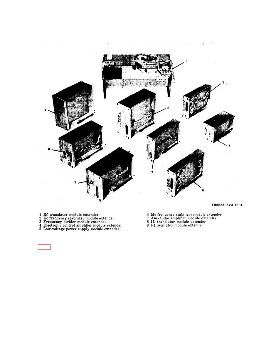
supply module A8 and power amplifier module
tenders are included, one for each module in the
A11.
receiver-transmitter, except high-voltage power
(2) Test lead W2. Test lead W2 is a single-
c. Cables, Test Leads, and Adapters (fig.
conductor, rubber-covered cable, 2 feet
adapters are provided as components of the
long, with a white jack tip at each end.
maintenance kit. Each cable is identified by a
(3) Test lead W3. Test lead W3 is a single-
metal band with the short nomenclature
conductor, rubber-covered cable, 2 feet
stamped on it. Following is a description of the
long, with a brown jack tip at each end.
cables, test leads, and adapters:
(4) Test lead W4. Test lead W4 is a single-
(1) Test lead W1. Test lead W1 is a single-
conductor, rubber-covered cable, 2 feet
conductor, rubber-covered cable, 2 feet
long, with a red jack tip at each end.
long, with an orange jack tip at each
(5) Test lead W5. Test lead W5 is a single-
end.
7
|
|
Privacy Statement - Press Release - Copyright Information. - Contact Us |