 |
|||
|
|
|||
|
Page Title:
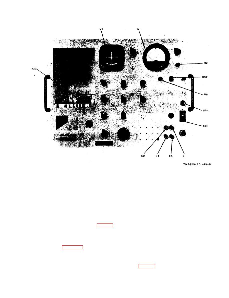
Figure 2-1. Test Set, Radio TS-1967/ARC-54, front panel view, parts location. |
|
||
| ||||||||||
|
|
 TM 11-6625-601-34
Figure 2-1. Test Set, Radio TS-1967/ARC-54, front panel
view, parts location.
switches S10 to RADIO and S11 to TEST SET.
p e r c e n t ) resistor between pins 2 and 4 of
(f) Set RCVR/XMTR FUNCTION switch
HEADSET jack J7.
S9 to PTT. (All other switches may be in any
(b) Apply +27.5 1 volts dc to test set
position.)
POWER jack J32.
(g) Apply a 1,000-Hz, 0.135-millivolt (mv),
(c) Set test set POWER circuit breaker to
root-mean-square (rms) signal between pins 3
ON.
(high) and 1 (low) of HEADSET jack J9. (To
(d) S e t t e s t s e t T E S T F U N C T I O N
obtain the 0.135-mv rms signal, apply 135 mv
SELECTOR switches S10 to SIM, and S11 to
rms across a 1,000-to-l voltage divider (fig. 2-13).
TEST SET.
(h) Connect the vtvm between pins 5 and
(e) S e t
test
set
RCVR2)XMTR
6 of RCVR/XMTR jack J11. Note that 390 mv
FUNCTION switch S9 to TEST.
rms is indicated on the vtvm. If this reading is
(f) Set the simulator HEADSET VOL con-
not obtained, perform the audio amplifier ad-
trol fully clockwise.
justment procedure (para 2-20).
(g) Apply a 1,000-Hz, 0.135-mv rms signal
(2) Voltage
measurements
for
audio
between pins 3 (high) and 1 (low) of HEADSET
amplifier card A1 (part of Simulator-Test Set
jack J7. (To obtain the 0.135-mv rms signal,
SM-349/ARC-54).
apply 135 mv rms across a 1,000-to-1 voltage
(a) Connect a 10-ohm (22-watt, 10-
divider (fig. 2-13).
2-3
|
|
Privacy Statement - Press Release - Copyright Information. - Contact Us |
