 |
|||
|
|
|||
|
|
|||
| ||||||||||
|
|
 C2, TM 11-6625-564-45
4-5. Test Unit Test
a. Test Equipment and Materials.
(1) Voltmeter, Meter ME-30(*)/U.
(2) Multimeter ME-26B/U.
(3) Audio Oscillator TS-421/U.
(4) Charger, Battery PP-1451/U.
(5) Matching pad, 600-ohm/5-ohm (C, fig. 4-1).
(6) Resistor, 9.5-ohm, 1/2-watt (two required).
(7) Radio set simulator (part of maintenance kit).
(8) Dummy load (part of maintenance kit).
(9) Cables W1, W2, W3, W5 (part of maintenance kit).
b. Test Connections and Conditions.
(1) Remove the dust covers from the test unit of a radio set simulator known to be good.
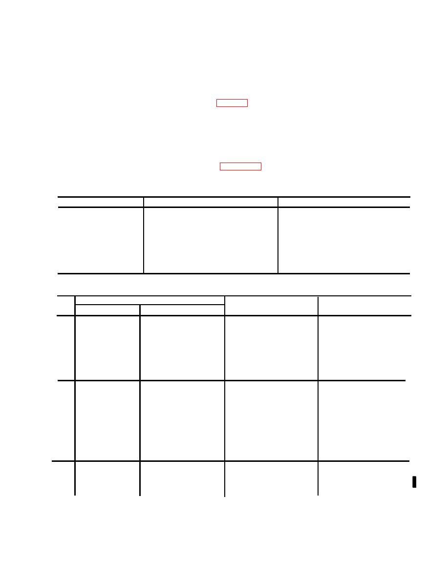
(2) Connect the test setup as shown in figure 4-2.
(3) Set the switches and controls on the front panels of the test unit and the radio set simu-
lator as indicated in the chart below.
Item
Position
Switch or control
Test unit
POWER switch
OFF
Test unit
OFF
PTT switch
Test unit
OFF
RF DET switch
Test unit
MIC SELECT switch
HDSET
Test unit
FUNCTION SELECT switch
OFF
Test unit
Fully clockwise
AUDIO GAIN control
Radio
set simulator
POWER switch
OFF
Radio
set simulator
OFF
XMIT LOAD switch
Radio
set simulator
OFF
TEST SELECT switch
Radio
set simulator
Fully clockwise
AUDIO GAIN control
c. Procedure.
Control setting
Step
NO.
Performance standard
Test Equipment
Equipment under test
Test
procedure
1
Radio set simulator
Test Unit
a. None.
a. POWER: RE-
a. POWER: RESET ON.
a. Turn on battery charger
SET ON.
and adjust output for
+27.5 vdc.
b. TEST SE-
b. T/R indicators will light.
b. Observe T/R indicator
b. FUNCTION SELECT:
LECT: RE-
T/R.
on test unit and T/R
MOTE SENS.
indicator on radio set
simulator.
2
a. Vary setting of test unit a. Meter must read in green
Controls remain as
Controls remain as at end
band of scale A at
at end of step 1.
of step 1.
SENSITIVITY con-
some setting of SEN-
trol, and observe me-
SITIVITY control.
ter on radio set simu-
lator.
b. Rotate test unit SENSI- b. SQ. DIS indicator will
light.
TIVITY control to SQ
DIS, and observe SQ.
DIS indicator on radio
set simulator.
3
ME-26B/U
a. Meter must read in
Controls remain as at end
a. Observe meter on radio
green band of scale A.
of step 1.
set simulator.
Set to the +300
vdc scale.
71
|
|
Privacy Statement - Press Release - Copyright Information. - Contact Us |
