 |
|||
|
|
|||
|
|
|||
| ||||||||||
|
|
 C2, TM 11-6625-564-45
the bracket on which the readout
check the dials for centering of the
mechanism is mounted.
correct numerals ((10) above) and
(12) Apply glyptal (b (2) above) to the
for axial clearance ( (11) above) after
channeling.
setscrews, and tighten the two set-
screws on each dial. If necessary,
(13) Set the POWER switch on the test
channel the readout mechanism to
unit and the POWER switch on the
different frequency settings to make
radio set simulator to OFF.
the setscrews accessible. Always re-
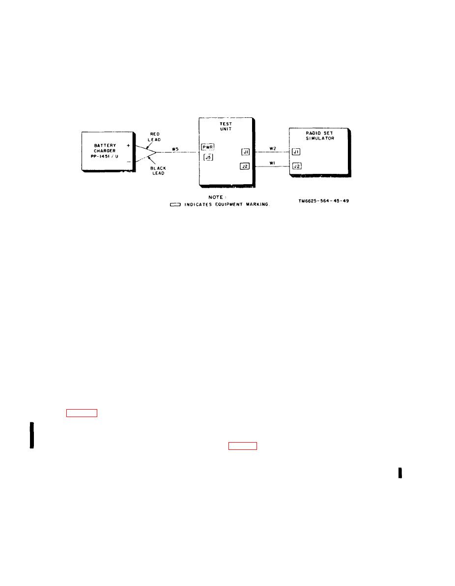
Figure 3-1. Radio set simulator, readout mechanism dial adjustment, test setup..
ALIGNMENT
Section II.
3-4. General
(1) POWER switch to OFF.
(2) XMIT LOAD switch to OFF.
This section contains alignment procedures
(3) TEST SELECT switch to VSWR
for the maintenance kit. Only uhf test gener-
CAL.
ator 1A5 of the radio set simulator requires
(4) VSWR CAL. control to midrange.
alignment.
c. Connect the equipment as shown in fig-
ure 3-2.
3-5. lest Equipment Required for
d. Place test unit POWER switch to RESET
Alignment
ON.
Charger,
PP-1451/U (battery
Battery
e. Place radio set simulator power switch
charger) is the only test equipment required
to RESET ON.
for alignment of the uhf test generator. All
f. Adjust output of PP-1451/U to 27.5 volts
additional equipment that is required is part of
dc.
the maintenance kit.
Note: If necessary, the procedure given in g below,
adjust radio set simulator VSWR CAL. control to keep
3-6. Uhf lest Generator Alignment
the needle of the meter on the front panel of the radio
set simulator in approximate center of the meter scales.
a. Remove radio set simulator dust cover
g. In the following order, adjust coil L1, ca-
and disassemble until uhf. test generator is
pacitor C10, capacitor C15, and capacitor C19
accessible. Set the switches on the front
panel of the test unit as follows:
cated on the meter on the radio set simulator.
Repeat these adjustments several times
(1) POWER switch to OFF.
starting with coil L1 each time.
SELECT switch to
(2) FUNCTION
h. Place test unit POWER switch and radio
OFF.
set simulator POWER switch to OFF. Dis-
b. Set the controls and switches on the front
connect all cables.
panel of the radio simulator as follows:
64
|
|
Privacy Statement - Press Release - Copyright Information. - Contact Us |
