 |
|||
|
|
|||
|
Page Title:
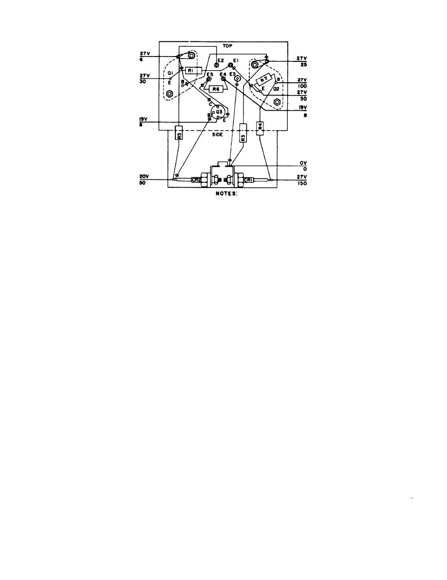
Figure 2-16. Radio set simulator, transient blanker module IA4, voltage and resistance measurement diagram. |
|
||
| ||||||||||
|
|
 TM
11-6625-564-45
1.
VOLTAGE READINGS ARE ABOVE THE LINE; RESISTANCE
READINGS ARC BELOW.
2. UNLESS OTHERWISE INDICATED. ALL VOLTAGES ARE DC,
AND ALL RESISTANCE VALUES ARE IN OHMS.
5 DO NOT ATTEMPT TO MAKE RESISTANCE MEASUREMENTS
WITH POWER ON.
4. ALL RESISTANCE MEASUREMENTS TAKEN FROM TEST
POINT TO GROUND WITH MULTIMETER ME-26B/U.
5. ALL DC MEASUREMENTS TAKEN FROM TEST POINT TO
GROUND WITH MULTIMETER ME-26B/U AND NO
SIGNAL INPUT.
TM6625-564-45-53
Fiqure 2-16. Radio set simulator, transient blanker module IA4, voltage and
resistance measurement diagram.
40
|
|
Privacy Statement - Press Release - Copyright Information. - Contact Us |
