 |
|||
|
|
|||
|
Page Title:
Section II. TROUBLESHOOTING SIMULATOR-TEST SET, RADIO SM-348/ARC-51X |
|
||
| ||||||||||
|
|
 TM 11-6625-564-45
If present, this type of trouble often
in locating the troublesome
stage
may be made to appear by tapping or
quickly.
jarring the equipment. Check the
23. Tools and Test Equipment Required
cables, wiring, and connections of the
The following tools and test equipment are
maintenance kit.
(6) Stage gain procedures. The stage
required for troubleshooting the maintenance
kit. The associated technical manuals and as-
gain procedures given in paragraphs
signed common names are also listed.
2-5 and 2-8 will aid the technician
Test equipment
Technical manual
Common name
TM 11-6626-200-12
Multimeter ME-26B/U
Test Set, Transistor TS-1336/U
Transistor teat set
Toolkit
Tool Kit, Radar and Radio Repair
SM 11-4-5180-R08
TK-87/U
Headset H-101A/U
Headset
Audio Oscillator TS-421/U
Audio oscillator
Voltmeter, Meter ME-30(*)/Ua
TM 11-6626-320-12
Tube tester
Test Set, Electron Tube TV-7/U
TM 11-6626-274-12
a. lncludes Vo1tmeter, Meter ME-30A/U and Voltmeters, Electronic ME-80B/U and ME-8OC/U.
Section II. TROUBLESHOOTING SIMULATOR-TEST SET,
RADIO SM-348/ARC-51X
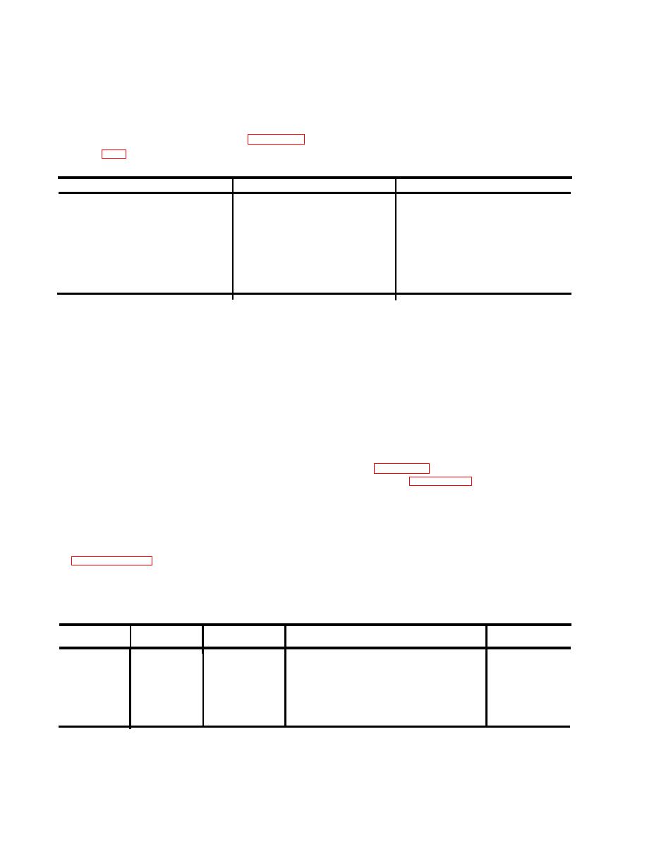
2-4. Resistance and Continuity
a. Disconnect all cables from the radio set
simulator.
Measurements
b. Remove the dust cover from the radio set
Make the resistance and continuity measure-
simulator.
ments indicated below. If results other than
c. Set the switch or switches shown in the
those indicated are obtained, isolate the
Switch column to the positions shown in the
faulty part by further resistance measurements
Position column. Connect the dc voltmeter
before making further tests or applying power.
between the terminal in the Terminals column.
Refer to figure 4-8, radio set simulator sche-
Cautions:
1. This equipment is partially transistorized.
matic diagram, figure 4-12, radio set simula-
Observe all precautions to prevent transistor
tor wiring diagram; and to the figures refer-
damage. Make resistance measuremnts in the
enced in the Figure column for terminal and
radio set simulator only as specified.
component location. All resistance readings
should be within 10 percent of those shown in
2. Do not attempt removal or replacement
the Resistance column. These measurements
of parts before reading the instructions given
are to be made before applying power to the
unit to insure complete chassis wiring contin-
Note: Unless otherwise indicated, references to test
uity and to localize the trouble before detailed
points, jacks, connectors, and switches apply to the
troubleshooting is performed.
radio net simulator.
Switch
Position
Terminals
Figure
Resistance
(ohms)
A of J2 to 6 of relay K2 ------------
POWER
RESET ON
2-1
0
A o f J 2 t o 4 o f r e l a y K 2 --------------
TEST SELECT
OFF
2-1
0
0
A o f J 2 t o point No. 1 of readout
2-1 and 2-3
mechanism.
A o f J 2 t o 3 s w i t c h S 1 B ---------------
28,700
2-1
A o f 5 2 t o T o f 5 2 ------------------------------
300
2-1
20
|
|
Privacy Statement - Press Release - Copyright Information. - Contact Us |
