 |
|||
|
|
|||
|
|
|||
| ||||||||||
|
|
 TM 11-6625-564-45
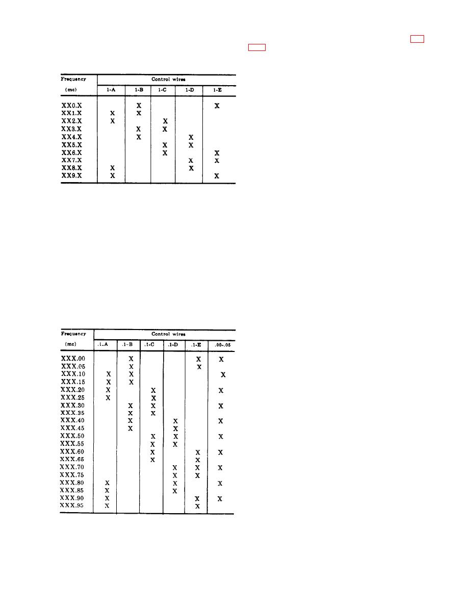
carries a ground for that particular freqrency
h. For the tens-digit Autopositioner (fig.
selection. No marks in a column indicates that
4-9) to operate, a ground must be applied
that control wire is not grounded.
through at least one of the tens-digit control
wires (10-A through .10-E), through switch
segment S2 rear, to motor-control relay K2.
This ground through segment S2 rear can be
direct from control wires 10-C, 10-D, and 10-
E (which are connected directly to segment
S2 rear), from control wire 10-A (connected
to segment S3 front), or from control wire 10-
B (connected to segment S3 rear). When a
ground is applied to motor-control relay
K2, relay K2 is energized and contacts 4 and
7 of the relay are closed. This condition ap-
plies +27.5 volts dc to diode CR2 and to sole-
noid L2. Diode CR2 then conducts, and the
+27.5 volts dc is applied to motor-control re-
g. The chart below shows the coding ap-
lay KS and causes KS to energize and close
plied to the control wires for tenths-digit and
contacts 4 and 7 of the relay. When contacts 4
hundredths-digit frequency selection. The five
and 7 of motor-control relay KS are closed,
control wires for tenthsdigit frequency selec-
+ 27.5 volts dc is applied to motor B1. Motor
tion are designated .1-A through .1-E, and the
B1 then starts, and the motor rotates the
single control wire for hundredths-digit fre-
gear `train. When the +27.5 volts dc is ap-
quency selection is designed .00-.05. The five
plied to solenoid L2, the solenoid energizes
columns designated .1-A through .1-E are ref-
and lifts the pawl out of a notch in the stop
erenced to the first digit to the right of the
wheel. This action allows the rotation of the
decimal point in the Frequency (mc) column.
gear train to be coupled through the slip clutch
The single column designated .00-05 is refer-
to the segments of switches S2 and S3, and to
enced to the second digit to the right of the
the tens dial.
decimal point in the Frequency (mc) column.
i. The gear train rotates the tens dial and
the segments of switches S2 and S3 until all
groundpaths through S2 and S3 to motor-con-
trol relay K2 are open. When all groundpaths
are open, motor-control relay K2 deenergizes,
and contacts 4 and 7 of the relax open. This
condition removes the +27.5 volts dc from sole-
noid L2, solenoid L2 then deenergizes, and the
pawl drops into a notch of the stop wheel to
prevent further rotation of the tens dial and
switches S2 and S3. The tens dial is now pos-
itioned to indicate the tens digit of the new
frequency. Also, when motor-control relay K2
deenergizes, diode CR2 ceases to conduct, mo-
tor-control relay K5 deenergizes, and contacts
4 and 7 of relay K5 open to cause motor B1 to
stop. Any residual energy of the motor coast-
ing to a stop is dissipated by the slip clutch.
j. To illustrate the groundpaths applied
through the tens-digit control wires (10-A)
through 10-E), assume that the tens-digit Au-
topositioner is set for a frequency readout of
13
|
|
Privacy Statement - Press Release - Copyright Information. - Contact Us |
