 |
|||
|
|
|||
|
Page Title:
Preliminary In-Aircraft Starting Procedure for Radio Set Simulator |
|
||
| ||||||||||
|
|
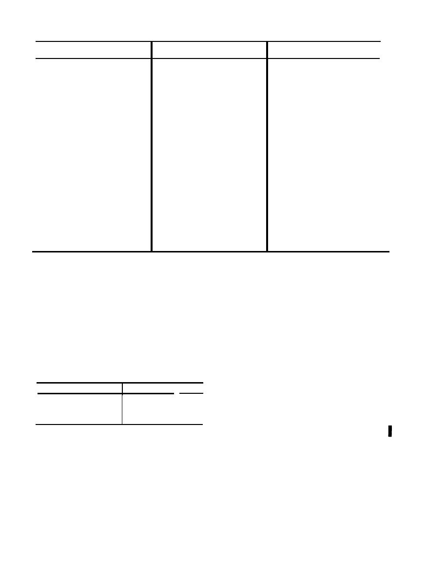 C2, TM 11-6625-564-12
Cable or
Connection
Connection
To
From
cable adapter
P1 on receiver-transmitter module
J2 on receiver-transmitter chassis
Cable W7
A2
P1 on receiver-transmitter module
Cable W8
J3 on receiver-transmitter chassis
A3
P1 on receiver-trasmitter module
Cable W8
J4 on receiver-transmitter chassis
A4
P1 on receiver-transmitter module
Cable W8
J6 on receiver-transmitter chassis
A6
P1 on receiver-transmitter module
Cable W8
J8 on receiver-transmitter chassis
A8
P1 on receiver-transmitter module
Cable W9
J5 on receiver-transmitter chassis
A5
P1 on receiver-transmitter module
Cable W9
J7 on receiver-transmitter chassis
A7
P1 on receiver-transmitter module
Cable W10
J9 on receiver-transmitter chassis
A9
Receiver-transmitter module
Cable W11
Reciver-transmitter chassis
coaxial connectors
coaxial connectors
Cable W12
Receiver-transmitter module
Test equipment BNC connectors
coaxial connectors
Cable W13
Receiver-transmitter module
Test equipment BNC connectors
coaxial connectors
Cable W1 a
Control cable adapter
Radio set control cable
Cable W2 a
Frequency selector cable adapter
Aircraft frequency cable
Cable W3 b
Rf cable adapter
Aircraft rf cable
a Cables W1 and W2 aare also used in the aircraft as an extension between the aircraft control cales and jacks
J1 and J2 on the radio set simulator.
b Cables W3 is used in the aircraft as an extension between the aircraft antenna cable and jack J3 on the
radio set simulator.
2-5. Preliminary In-Aircraft Starting
2-6. Stopping Procedure for Radio Set
Procedure for Radio Set Simulator
Simulator
Perform the following procedures to remove
Perform the operations listed below before
radio set simulator from operation:
starting the equipment.
a. Secure radio set simulator to the receiver-
a. Turn TEST SELECT switch to OFF.
transmitter mounting in the aircraft.
b. Set POWER switch to OFF.
b. Set the radio set simulator controls to the
c. Set radio set control FUNCTION SE-
positions listed in the following chart.
LECT switch to OFF.
d. Disconnect cables from jacks Jl, J2, and
J3.
Position
Control
e. Disconnect headset from HEADSET H-
OFF
POWER
101 A U jack.
OFF
TEST SELECT
OFF
XMIT LOAD
Preliminary Starting Procedure for
2-7.
c. Connect aircraft cable cnnectors P1 and
the Test Unit
P2 to jacks J1 and J2, respectively, on the ra-
Perform the operations listed below before
dio set simulator.
starting the equipment.
a. Control Settings. Set the test unit con-
jack J3 on the radio set simulator,
trols to the positions listed in the following
e. Plug the headset into the radio set simu-
chart:
lator HEADSET H-101 A U jack.
24
|
|
Privacy Statement - Press Release - Copyright Information. - Contact Us |
