 |
|||
|
|
|||
|
Page Title:
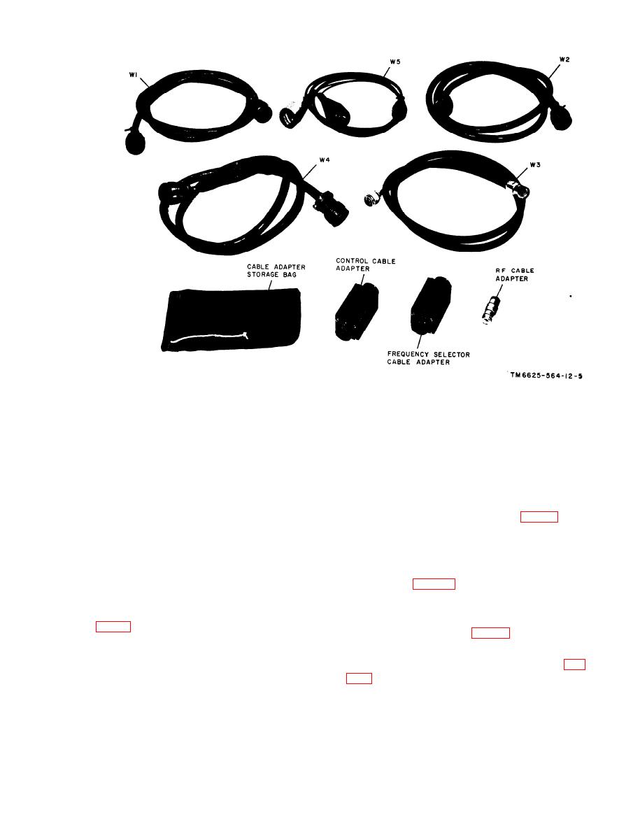
Figure 1-6. Main Cables, cable adapters, and cable adapter storage bag. |
|
||
| ||||||||||
|
|
 C 2, TM 11662556412
Figure 1-6. Main Cables, cable adapters, and cable adapter storage bag.
and spectrum generator module A5 during the
with a 25-pin male connector on one end, and
alignment of their gear trains. The locking
a 25-pin female connector on the other end.
block attaches to the base of first and second
(6) Cable W11. Cable W1l is a coaixial
intermediate frequency (if.) amplifier module
vinyl-covered cable, 18 inches long, with a male
A2, to hold the if. at 25 megacycles during
microdot connector on one end and a female
alignment of the preamplifiers.
microdot connector on the other end.
(7) Cablc W12. Cable W12 is a coaxial
vinyl-covered cable, 18 inches long, with a fe-
dummy load provides the transmitter with a
male microdot connector on one end and a fe-
load of 50 ohms for use during transmitter
male BNC connector on the other end.
testing. The adjustable whip antenna is used
(8) Cable W13. Cable W13 is a coaxial
during receiver-transmitter testing.
vinyl-covered cable, 18 inches long, with a male
microdot connector on one end and a female
the special tools necessary for the use of the
BNC connector on the other end.
maintenance kit by the technician. The running
e. Alignment Fictures and Locking Block
spares consisting of eight panel lamps and one
100-megacycle crystal (fig. 12) are stored in
trum generator alignment fixture, power ampli-
the toolkit bag.
fier alignment fixture, and receiver-preamplifier
alignment fixture, are used to hold the coupler
halves of power amplifier module A6, receiver
is an aluminum framework with two wingnut
radiofrequency (rf) preamplifier module Al,
11
|
|
Privacy Statement - Press Release - Copyright Information. - Contact Us |
