 |
|||
|
|
|||
|
Page Title:
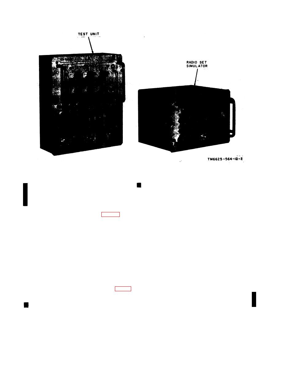
Figure 1-3. The major component of the maintenance kit. |
|
||
| ||||||||||
|
|
 C 2, TM 11-6625-564-12
Figure 1-3. The major component of the maintenance kit.
band located on the cable. The following is a
provides access to a space containing test cables,
description of the main cables and adapters:
tools, cable adapters; technical manuals, and a
(1) Cable W1. Cable W1 is a 26-conductor
dummy load (MK-731A/ARC-51X only). The
rubber-covered cable, 5 feet long, with a 26-
two halves are fastened together by four twist-
pin female connector on each end.
lock clamps.
(2) Cable W2. Cable W2 is a 26-conductor
rubber-covered cable, 5 feet long, with a 26-pin
rigid module extenders are aluminum castings,
female connector on each end.
in the shape of the modules they replace, that
elevate the receiver-transmitter modules so
(3) Cable W3. Cable W3 is a coaxial cable,
modules can be worked on while still being
5 feet long, with a male connector on each end.
electrically and mechanically connected to the
(4) Cable W4. Cable W4 is a 32-conductor
receiver-transmitter. They also provide test
rubber-covered cable, 5 feet long, with a 32-pin
points for monitoring all electrical leads except
female connector on each end.
the coaxial type. The eight rigid module ex-
(5) Cable W5. Cable W5 is a two-conduc-
tenders, one for each module in the receiver-
tor rubber-covered cable, 6 feet long, with a
transmitter except mechanical tuner module A9,
three-pin male connector on one end and two
are stored in the rigid module extender mount-
alligator clips on the other end.
ing tray.
(6) Cable adapters. The control and fre-
quency selector cable adapters have a 26-pin
Five main cables and three adapters are pro-
male connector at each end. The rf cable adap-
vided with the maintenance kit. Each cable is
ter has a female connectyor on each end. These
identified by short nomenclature stamped on a
8
|
|
Privacy Statement - Press Release - Copyright Information. - Contact Us |
