 |
|||
|
|
|||
|
Page Title:
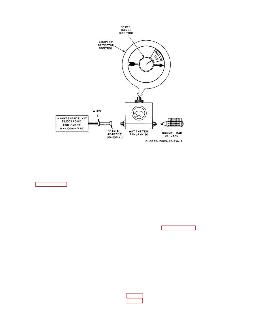
Figure 2-4. Wattmeter, Radio Frequency AN/URM-120 connected to maintenance kit. |
|
||
| ||||||||||
|
|
 TM 11-6625-2609-12
connected to maintenance kit.
(10) Repeat step (4) above. Sidetone should
(4) Settle PTT switch to OFF.
be present, power should be inflicted on the
f. Sidetone Check. Start the equipment as
AN/URM-120, sidetone should be indicated on
instructed in paragraph 2-6 and proceed as fol-
t h e ME-30A/U, and INPUT CURRENT meter
lows :
should indicate changing current levels.
(1) Leave the AN/URM-120 connected as
(11) Set the selector switch to position 4.
described in e above.
(12) Repeat step (4) above. There should be
(2) Connect the ME-30A/U to the SIDE-
no sidetone or power indication.
TONE OUTPUT jacks.
(13) Set the selector switch to position 3.
( 3 ) Set the transmit-interphone selector
g. Modulation Checks. Start the equipment
switch to PVT.
as instructed in paragraph 2-6 and proceed as
(4) Key the AN/ARC-134 with the U-94A/
follows :
U and talk into the microphone. Sidetone should
( 1 ) Leave the AN/URM-120 and Dummy
be present in the headset and no power should be
Load DA-75U connected as described in e above.
indicated on the AN/URM-43A or the ME-30A/
(2) Set the AN/ARC-134 meter switch (fig.
U.
2-3) to MOD I 10A FS.
( 5 ) Set the transmit-interphone selector
(3) Key the AN/ARC-134 with the U-94A/
switch to position 1.
U. Talk into the microphone and observe the
AN/ARC-134 meter. The meter should fluctuate
(6) Repeat step (4) above. There should be
with modulation.
no sidetone and no power indication on the ME-
30A/U or the AN/URM-120.
( 4 ) Connect Signal Generator AN/URM-
127 through a 50-micro farad blocking capacitor
(7) Set the selector switch to position 2.
(8) Repeat step (4) above. There should be
no sidetone or power indication.
(5) Set the AN/URM-127 to a frequency of
1000 Hz.
(9) Set the selector switch to position 3.
|
|
Privacy Statement - Press Release - Copyright Information. - Contact Us |
