 |
|||
|
|
|||
|
Page Title:
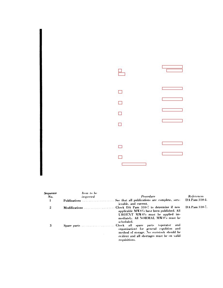
Quarterly Preventive Maintenance Checks and Services Chart |
|
||
| ||||||||||
|
|
 TM 11-6625-1635-12
C1
Sequence
Item to be
References
Procedure
inspected
No.
VHF COMM VOL control. . . . . . . . Leave equipment adjusted as described in
18
sequence No. 17. Vary VHF COMM VOL
control from minimum to maximum. Signal
in the headset should increase as control is
turned maximum clockwise.
I n t e r c o m c o n t r o l V O L c o n t r o l Leave equipment adjusted as described in
19
(maintenance kit modified only)
s e q u e n c e 17. Vary VOL control from
minimum to maximum. Signal in H-
1 0 1 A / U should increase as control is
turned clockwise.
PTT switch. . . . . . . . . . . . . . . . . . . . . . Perform the procedure given in paragraph 2-
20
observed on the AN/URM-43A and, on
the maintenance kit modified, the dc am-
meter should indicate between 6 and 9 amps.
MIKE jack (maintenance kit un- Perform the procedure given in paragraph 2-
21
modified)
heard in the H-216/U.
SIDETONE jack (maintenance kit Perform the procedure given in paragraph 2-
22
unmodified)
sidetone should be heard in the headset.
MIKE INPUT jack (maintenance Perform the procedure given in paragraph 2-
23
kit unmodified)
should be observed in the AN/ARC-134.
Transmit-Interphone Selector Switch Perform the procedure given in paragraph 2-
24
(maintenance kit modified only)
interphone selector switch is in Position
INT.PVT. and 3. Power output should be
observed on the AN/URM-43A only when
the selector switch is in position 3.
DBM INPUT jacks. . . . . . . . . . . . Perform the procedure given in paragraph 2-
25
observed on yhe AN/AQRC-134 meter.
DATA LINK INPUT jacks . . . . . . Perform the procedure given in paragraph 2-
26
obtained on the AN/ARC-134 meter.
See paragraph 6i. Modulation should be
27
DETECTOR METER
indicated by a meter deflection on the TS-
DETECTOR INPUT and
352/B/U and by an increase in the
SCOPE OUTPUT jacks
AN/URM-43A indication.
3-7. Quarterly Preventive Maintenance Checks and Services Chart
App B.
3-3
|
|
Privacy Statement - Press Release - Copyright Information. - Contact Us |
