 |
|||
|
|
|||
|
Page Title:
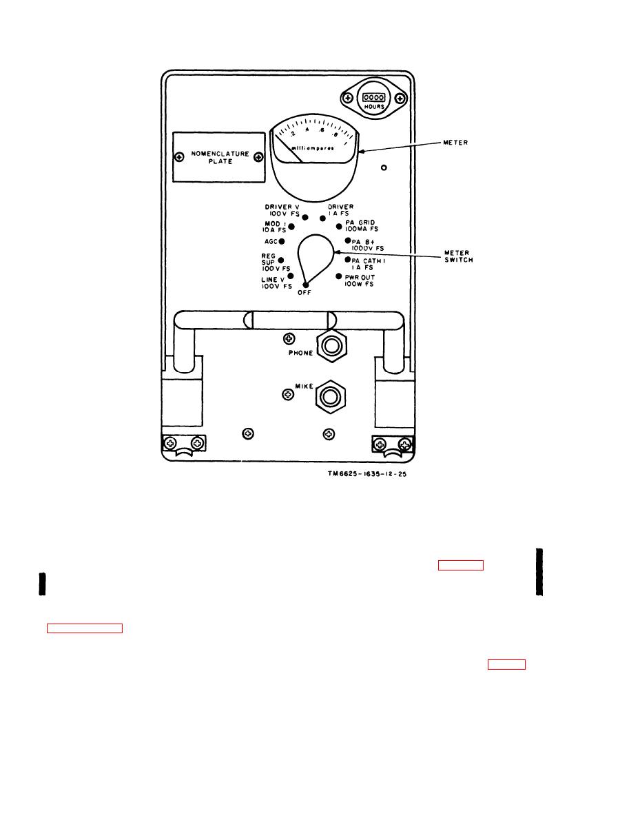
Figure 2-4. Radio Set AN/ARC-134, front panel view. |
|
||
| ||||||||||
|
|
 TM 11-6625-1635-12
C1
F i g u r e 2-4. Radio Set AN/ARC-134, front panel view.
2-6. Operational Checks
Caution. In (2) below, be sure to connect
the 700061-0001 fuse holder between the
The operational checks in a through h b e l o w
output receptacle of the AN/USM-44 and
are given to familiarize the operator with the use
antenna connector J1 (fig. 2-3) on the
o f the maintenance k i t . F o r t h e c o m p l e t e
m a i n t e n a n ce k i t . T h e f u s e h o l d e r s h o u l d b e
AN/ARC-134 test procedures, refer to TM 11-
equipped with a 70061-0002 fuse. Do not
5821-277-35.
p r e s s the PTT switch on the microphone or
a. Receiver Control Circuit Check at 132.5
t h e test panel when the very high frequency
M H Z . Start the equipment as instructed in
( v h f ) signal generator is connected to con-
nector J1.
( 1 ) Set Multimeter TS-352B/U to read
(2) Connect the AN/USM-44 to antenna
a l t e r n a t i n g current (at) volts and connect to
connector J1 on the maintenance kit (fig. 2-3).
RECEIVER OUTPUT jacks on the main-
Set
the
AN/USM-44
for
a
132.500-MHz
tenance kit.
2-8
|
|
Privacy Statement - Press Release - Copyright Information. - Contact Us |
